Digital Tachometer SELECTRONIC®
MT90 Model
• ±1 RPM Accuracy
• Easy Calibration
• Clear-Read LCD Display
• Back Light for Night Viewing (Battery Powered models)
• Input Source Can Be a Magnetic Pickup or Engine Alternator
• Power Supplied by Magnetic Pickup or 12, 24 or 32 VDC Battery System
Description
The Murphy SELECTRONIC® MT90 is a digital tachometer. Its high accuracy and dependability result from use of a quartz crystal time based and digital, solid-state electronics.
Tachometer power is supplied by either a Murphy magnetic pickup, mounted at the flywheel ring-gear of an engine, or by a 12, 24 or 32 volt DC battery system.
RPM data is supplied by either a Murphy magnetic pickup or by the alternator in your battery charging circuit. The MT90 also has back-lighting for easy readings in low lit areas; this lighting requires a battery power source.
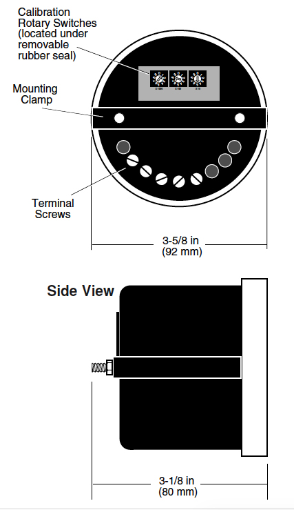
RPM Calibration
The MT90 is calibrated to engine RPM by setting a series of calibration rotary switches on the back of the tachometer. The proper switch sequence for the engine is determined by (1) the number of ring gear teeth for the magnetic pickup, or (2) by the ratio of alternator to engine pulley diameter, and the number of poles of the alternator.
Applications
Typical applications include: Generators, Compressors, Industrial Engines, Oil Field Equipment, Marine Vessels, Vehicles, Farm Equipment, and Construction Equipment.
Description
Specifications
Signal Input Voltage: 4 to 35 Vrms from a magnetic pickup or alternator**
Pulses per Revolution: 3 to 999
Power Requirements:
• Pickup Power: 4-35Vrms** • Battery Power: 8-40 VDC (12, 24, 32 volt)
Current: • Tach back-light Off, 4mA @ 40 VDC • Tach back-light On, 25 mA @ 40 VDC
Case: 1018 polycarbonate/polyester blend
Lens: Polycarbonate
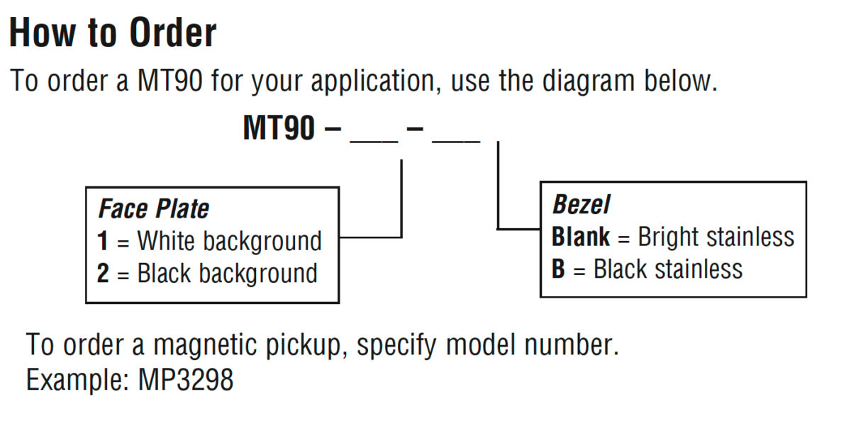
Bezel: #430 Stainless Steel
Display: LCD, 4-digit, seven segment
Operating Temperature: -4 to 158°F (-20 to 70°C)
Storage Temperature: -13 to 185°F (-25 to 85°C)
Mounting Hole: 3-7/16 in. (87 mm.)
Shipping Weight: 14 oz. (0.4 kg)
Shipping Dimensions: 5-1/2 x 5-1/2 x 5-1/2 in. (140 x 140 x 140 mm.)
Warranty
A two-year limited warranty on materials and workmanship is given with this Murphy product. Details are available on request and are packed with each unit.
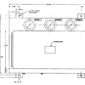
Dimensions
* Products covered by this bulletin comply with EMC Council directive 89/336/EEC regarding electro- magnetic compatibility except as noted.
**See “Special Note” for Magnetic Pickup Powered MT90 applications (below).
Typical Wiring Diagrams for MT90 Terminal 2: connects to battery (-) or ground Terminal 3: connects the back-light to battery (+), (back-light can only be used when powering from battery) Terminal 4: connects to battery (+) or power from magnetic pickup or alternator Terminal 5: RPM input signal from magnetic pickup Terminal 6: RPM input signal from alternator
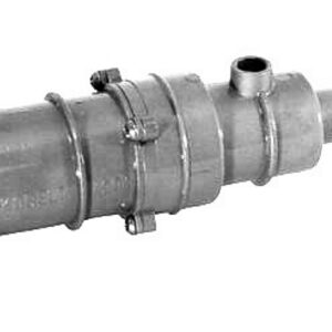
NOTE: Gap from face of gear tooth must be enough for gear to move. Rotate gear completely to be sure of minimum, no-touch clearance. See instructions supplied with the magnetic sensors. To get minimum of 4 VAC RMS, gap tolerance is critical. Turn the pickup in until it stops against the face of a gear tooth. Back the pickup out only enough to allow rotation of the gear. Rotate the gear, if any tooth touches the pickup, back it out to clear the tooth. After clear rotation secure the pickup locking nut.
NOTE: Gap from face of gear tooth must be enough for gear to move. Rotate gear completely to be sure of minimum, no-touch clearance. See instructions supplied with magnetic sensor. | Calibration To calibrate the MT90 for your engine, remove the rubber seal on the back of the tachometer and dial in the correct number. • Magnetic Pickup: dial in the number of teeth on your ring gear. Set the switches from left to right. For example, if the engine gear has 125 teeth, dial a 1 on the left switch, a 2 on the center switch, and a 5 on the right switch. Using this setting, the MT90 will count the passing teeth and convert them into engine RPM. • Alternator: Multiply the ratio of alternator to engine pulley diameter, times, the number of poles of the alternator divided by two, to determine the correct calibration number (also see “Other Calibration Methods”). Other Calibration Methods (teeth or ratio unknown) For setting the calibration switches when the number of pulses per revolution are not known, set the rotary switches on back of the MT90 to 0-6-0 and read the tachometer at a known engine RPM. This can be read by a hand-held tachometer or any means which tells actual RPM The reading is the input frequency in hertz. Multiply the frequency times 60 and divide the result by the engine RPM. Set this number into the rotary calibration switches. NOTE: If pulses per revolution are not a whole number, for example: 21.5, a setting of 021 will read slightly high and a setting of 022 will read slightly low. |
In order to consistently bring you the highest quality, full featured products, we reserve the right to change our specifications and designs at any time.