DIRECT MOUNT PRESSURE SWITCH
MODEL PSB
• Limit Switch for Critical Pressure
• Operate Alarms or Shutdown Equipment
• SPDT Snap-Acting Switch
• Fits Most Engine Applications
Description
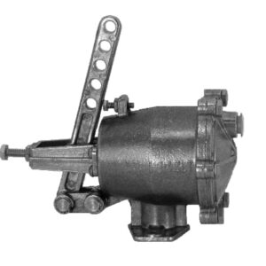
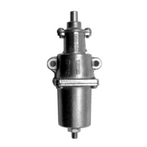
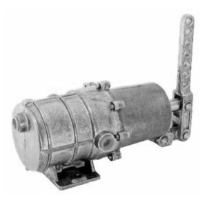
The PSB switch is a direct mount switch for critical pressure points. It has one limit contact that can be used to activate an alarm, actuate indicator lights or shutdown equipment.
The construction of this instrument is the same as our time-proven SWICHGAGE®. A precision machined brass mounting plate and port captures a high quality stamped beryllium copper diaphragm. The single-pole, double-throw (SPDT) snap-switch is operated directly from the diaphragm for quick acting and positive switching. Trip point is factory preset according to your specifications.
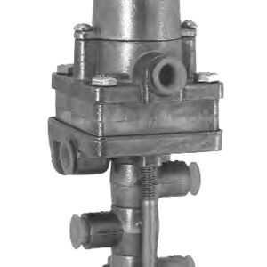
Housing is weather sealed to prevent entry of moisture, dust, etc. A glass-filled nylon terminal block with quick screw terminal connections gives the PSB switch a real advantage in industrial engine applications.The PSB is ideal when reading is not desired, but pressure is critical to operational efficiency.
Intended for use in general purpose non-classified areas.
Description
Applications
• Engine Lubrication
• Water pumps
• Compressors
• Oil field systems
• Irrigation systems
• Construction Equipment
• Mobile Equipment
• Marine engines • Generators
Features
• Fits all engine applications
• SPDT snap-switch
• Activates indicator lights, alarms, or shut down equipment
• Time-proven SWICHGAGE® construction
• Easy wiring terminal block
• Steel housing specially coated to resist corrosion
• Factory preset to your specifications
Specifications
Housing: Plated steel.
Pressure Connection: 1/8-27 NPT, Brass.
Diaphragm: Formed beryllium copper (heat treated).
Pulsation Dampener: Brass (it is removable for cleaning).
Terminal Block: Three #4-40 screws.
Accuracy: Trip point: ±3% of full scale. Switch reset differential: ±7% of full scale. Repeatability: ±1% of full scale.
Contact Rating: SPDT 3 A @ 30 VDC inductive.
Maximum Pressure: See Trip Point Chart on reverse side.
Temperature Range: Ambient= -40°F (-40°C) thru 150°F (66°C). Process= -40°F (-40°C) thru 250°F (121°C).
Factory Trip Point Setting: See Trip Point Chart.
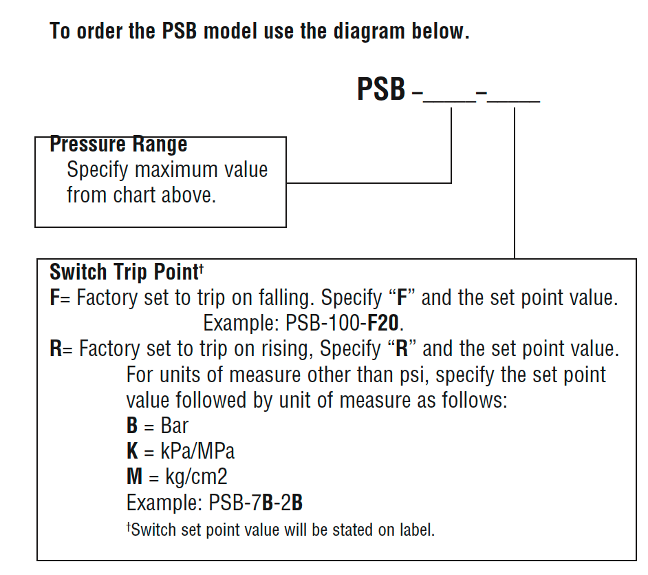
Pressure Range: Specify from 0-400 psi (0-2.76 MPa) [0- 27.58 bar].
Contact: Operates on rising or falling pressure (specify).
Shipping Weight: 8 oz. (0.25 kgs).
Shipping Dimensions: 3 x 2-3/4 x 2-3/4 in.(76 x 70 x 70 mm.).
NOTE: No customer replacement parts.
| Installation InstructionsMounting CAUTION: Use wrench on shank to tighten or loosen pressure connection. DO NOT TWIST CASE, which will damage the unit and void the warranty. 1. Before installing the PSB switch, apply sealant, such as Teflon tape, to the threads (be sure sealant does not block the inlet orifice). 2. The PSB can be mounted in horizontal or vertical angles (do not mount switch facing down). 3. Locate the unit in place and secure it by tightening the 1/8-27 NPT fitting into the desired location (do not over tighten). DO NOT TWIST CASE.
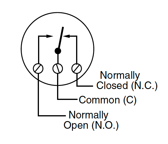
Wiring CAUTION: DISCONNECT Electrical power before wiring. 1. Switch contacts (below) are shown with no pressure applied to the PSB switch. 2. A spade (forked) terminal is recommended for all PSB switch connections. 3. Complete the wiring operation making sure the voltage and current requirements are within the PSB switch electrical rating (see the typical wiring diagram at right).
| |||||||||||||||||||||||||||||||||||||||