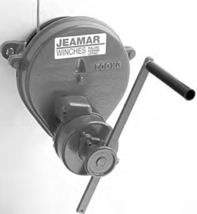
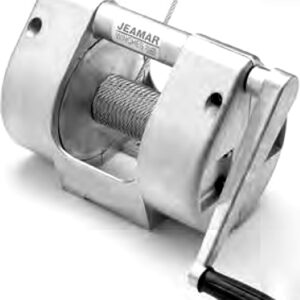
CFF SERIES CONTROLLED FREE FALL
CFF 660 / 1100 / 2200 / 3300
Controlled Free Fall
By simply pushing the handle back in the reverse direction, the winch will pay out at a controlled speed. The pay out speed is variable up to a predetermined maximum and is under the full control of the operator at all times. When the handle is released, the holding brake automatically goes on and the load is held.
Standard Double Braking System
A centrifugal dynamic brake is incorporated to govern maximum speed and to prevent overspeeding of the load. In addition, a load-activated brake is incorporated, allowing the operator to stop and hold the load securely in any position. This unique braking system also prevents the winch handle from recoiling.
High Rope-to-Drum Ratio
Rope life is substantially increased with drum diameters a minimum of 20 times the diameter of the rope.
Fully Enclosed Gears
All gears are fully enclosed, increasing operational protection and making the winch ideal for use in adverse conditions.
Description
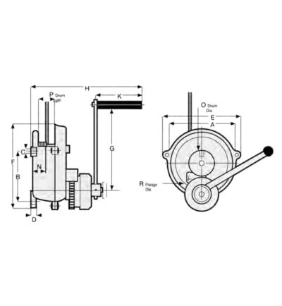
| Model Number | CFF 660 | CFF 1100 | CFF 2200 | CFF 3300 | ||
|---|---|---|---|---|---|---|
| Working Load Limit (1st Layer) | lb | 660 | 1100 | 2200 | 3300 | |
| kg | 300 | 500 | 1000 | 1500 | ||
| Rope Diameter | in | 3/16 | 1/4 | 3/8 | 7/16 | |
| mm | 5 | 6 | 9 | 11 | ||
| Rope Storage Capacity | ft | 85 | 67 | 50 | 45 | |
| m | 26 | 20 | 15 | 14 | ||
| Lift Per Crank Rotation | in | 3.0 | 2.72 | 1.42 | 1.18 | |
| mm | 76 | 69 | 36 | 30 | ||
| Hand Force Required At Maximum Load | lb | 22.7 | 33.9 | 36.1 | 44.7 | |
| N | 101 | 151 | 161 | 199 | ||
| Maximum Lowering Speed | ft/min | 118 | 118 | 59 | 59 | |
| m/min | 36 | 36 | 18 | 18 | ||
| Weight | lb | 75 | 110 | 191 | 242 | |
| kg | 34 | 50 | 87 | 110 | ||
| Dimensions | A | in | 10.43 | 13.19 | 13.58 | 14.76 |
| mm | 265 | 335 | 345 | 375 | ||
| B | in | 8.74 | 10.63 | 18.78 | 20.98 | |
| mm | 222 | 270 | 477 | 533 | ||
| C | in | 0.59 | 0.75 | 0.79 | 0.79 | |
| mm | 15 | 19 | 20 | 20 | ||
| D | in | 0.95 | 0.98 | 1.18 | 1.18 | |
| mm | 24 | 25 | 30 | 30 | ||
| E | in | 12.17 | 15.63 | 15.75 | 17.56 | |
| mm | 309 | 397 | 400 | 446 | ||
| F | in | 13.70 | 17.13 | 24.8 | 27.36 | |
| mm | 348 | 435 | 630 | 695 | ||
| G | in | 17.32 | 17.32 | 17.32 | 17.32 | |
| mm | 440 | 440 | 440 | 440 | ||
| H | in | 21.97 | 22.95 | 23.74 | 24.72 | |
| mm | 558 | 583 | 603 | 628 | ||
| K | in | 9.37 | 9.37 | 9.37 | 9.37 | |
| mm | 238 | 238 | 238 | 238 | ||
| N | in | 2.48 | 2.95 | 3.74 | 4.13 | |
| mm | 63 | 75 | 95 | 105 | ||
| O | in | 4.72 | 5.90 | 7.87 | 8.07 | |
| mm | 120 | 150 | 200 | 205 | ||
| P | in | 3.11 | 3.39 | 4.61 | 4.92 | |
| mm | 79 | 86 | 117 | 125 | ||
| R | in | 7.68 | 10.24 | 10.83 | 11.42 | |
| mm | 195 | 260 | 275 | 290 | ||
Automatic Brakes are Standard
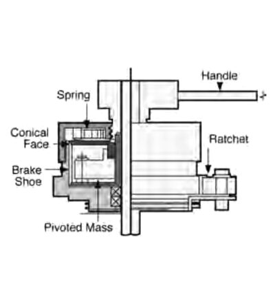
The brake mechanism uses a split-shoe brake acting against a cylindrical drum. Counterclockwise rotation of the handle releases the brake by removing the axial pressure at the conical faces. The load begins to fall and the pivoted masses swing out under centripetal acceleration and reapply the brake. Releasing the handle applies the brake for positive holding of the load. Ask for your copy of the technical bulletin on this Jeamar braking system.
Jeamar manufactures heavy duty winches for virtually any application. Thirteen different models are available in a wide range of sizes. Load activated brakes are standard on all models and sizes.
None.

