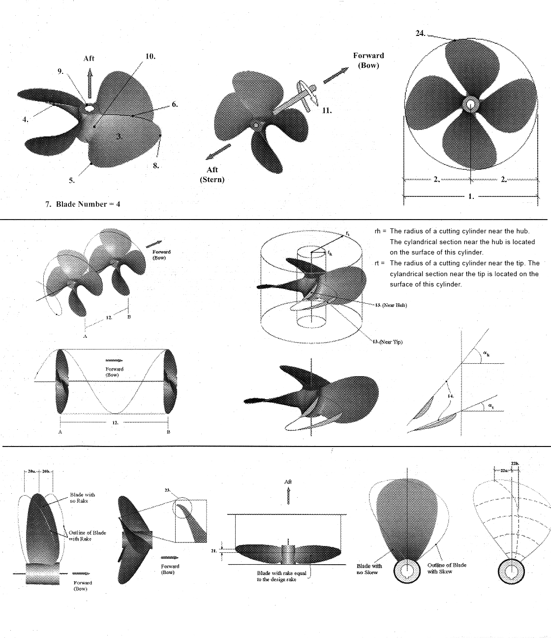
| 1. Diameter | The diameter of the imaginary circle scribed by the blade tips as the propeller rotates. |
| 2. Radius | The distance from the axis of rotation to the blade tip. The radius multiplied by two is equal to the diameter. |
| 3. Blade Face | Pressure Side, Pitch Side. Aft side of the blade (surface facing the stern). |
| 4. Blade Back | Suction Side. Forward side of the blade (surface facing the bow). |
| 5. Leading Edge | The edge of the propeller blade adjacent to the forward end of the hub. When viewing the propeller from astern, this edge is furthest away. The leading edge leads into the flow when providing forward thrust. |
| 6. Trailing Edge | The edge of the propeller adjacent to the aft end of the hub. When viewing the propeller from astern, this edge is closest. The trailing edge retreats from the flow when providing forward thrust. |
| 7. Blade Number | Equal to the number of blades on the propeller. |
| 8. Blade Tip | Maximum reach of the blade from the center of the hub. Separates the leading and trailing edges. |
| 9. Hub | Solid cylinder located at the center of the propeller. Bored to accommodate the engine shaft. Hub shapes include cylindrical, conical, radius & barreled. |
| 10. Blade Root | Fillet area. The region of transition from the blade surfaces and edges to the hub periphery. The area where the blade attaches to the hub. |
| 11. Rotation (Right hand shown here) | When viewed from the stern (facing forward): Right-hand propellers rotate clock wise to provide forward thrust. Left-hand propellers rotate counter-clockwise to provide forward thrust. |
| 12. Pitch | The linear distance that a propeller would move in one revolution with no slippage. |
| 13. Cylindrical Section | A cross section of a blade cut by a circular cylinder whose centerline is the propeller axis of rotation. |
| 14. Pitch Reference Line | Reference line used to establish the geometric pitch angle for the section. This line may pass through the leading and trailing edges of the section and may be equivalent to the chord line. |
| 15. *Geometric Pitch Angle, a | The angle between the pitch reference line and a line perpendicular to the propeller axis of rotation. |
| 16. *Controllable Pitch Propeller | The propeller blades mount separately on the hub, each on an axis of rotation, allowing a change of pitch in the blades and thus the propeller. |
| 17. *Fixed Pitch Propeller | The propeller blades are permanently mounted and do not allow a change in the propeller pitch. |
| 18. *Constant Pitch Propeller | The propeller blades have the same value of pitch from root to tip and from leading edge to trailing edge. |
| 19. *Variable Pitch Propeller | The propeller blades have sections designed with varying values of local face pitch on the pitch side or blade face. |
| 20. *Rake | The fore or aft slant of a blade with respect to a line perpendicular to the propeller axis of rotation. |
| 20a. Aft Rake | Positive Rake. Blade slant towards aft end of hub. |
| 20b. Forward Rake | Negative Rake. Blade slant towards forward end of hub. |
| 21. Track | The absolute difference of the actual individual blade rake distributions to the other blade rake distributions. Always a positive value and represents the spread between individual blade rake distributions. |
| 22. Skew | The transverse sweeping of a blade such that viewing the blades from fore or aft shows an asymmetrical shape. |
| 22a. Aft Skew | Positive Skew. Blade sweep in direction opposite of rotation. |
| 22b. Forward Skew | Negative Skew. Blade sweep in same direction as rotation. |
| 23. Cup | Small radius of curvature located on the trailing edge of blade. |
| 24. D.A.R. | Developed Area Ratio is blade area expressed as the percentage of a circle shaded by the propeller. |
| * denotes terms that do not have a graphic representation to aid in definition.” |