BILGE LEVEL SWITCH SYSTEM
BLSK1 Series
• Operates Bilge Pumps or Alarms
• Uses Proven “Air Cell” Actuated System
• Remote Switch and Moving Parts Kept Unaffected by Corrosion
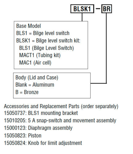
• Aluminum or Bronze Body and Cover
• Includes 3 Assemblies:
(1) BLS1 Bilge Level Switch
(2) MACT1 Tube Kit (Sensor Line and Fittings)
(3) MAC1 “Air Cell” (Volume Cell)
DESCRIPTION
The BLSK1 Bilge Level Switch System gives you all items and fittings necessary to install in your bilge. Or, you can have only the parts you want and you provide brackets, tubing and mounting hardware.
Using the proven “Air Cell” actuating system, all moving parts and switching are remote from bilge liquids and are thus not affected by corrosion, rust, etc. All wetted parts are of non-corrosive materials.
As bilge level rises a column of air is captured in the MAC1 Air Volume Cell. The rising bilge level compresses the column of air creating pressure against the large diaphragm in the BLS1 Bilge Level Switch and the switch trips. Switch set point is adjustable.
The switch resets as the bilge is pumped out. Air cell recharges itself during normal operation.
The BLS1 is constructed of materials not affected by marine atmospheres; Aluminum or Bronze body and cover, Buna-N diaphragm.
Description
Specifications
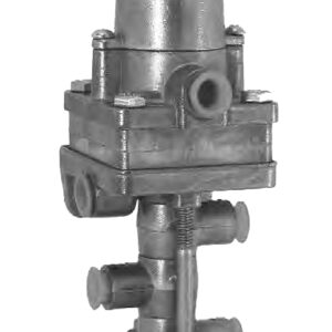
BLS1 Bilge Level Switch
Snap-Switch SPDT (standard)
• 5 A @ 125, 250, or 480 VAC
• 1/2 A @ 125 VDC, 1/4 A @ 250 VDC
NOTE: A pilot relay may be used for higher contact ratings (see Typical Wiring Diagram).
Case/Lid: Aluminum (std); Bronze (optional).
Bottom Plate: Glass-filled Nylon.
Process Connection: 1/4 NPTF.
Max. Pressure: 25 psi (172 kPa) [1.72 bar].
Conduit Connection (electrical): 1/2 NPT.
BLS1 Weight: 3 lb. (1.4 kg).
BLS1 Weight (Bronze): 6.5 lb. (2.9 kg).
BLS1 Dimensions: 6-1/4 x 6-1/4 x 6-1/4 in. (159 x 159 x 159 mm.).
15050737 Optional mounting bracket16 ga., 304 stainless steel (see Dimensions).
MACT1 Tube Kit (fittings included): 4 ft. (1.21 m) flexible non-corrosive tubing, 1/4 in. (6 mm.) dia. (cut to fit).
MACT1 Weight: 0.5 lb. (0.23 kg).
MACT1 Dimensions: 6 x 6 x 6 in. (152 x 152 x 152 mm.).
MAC1 Air Cell (Volume Cell)
• Made of non-corrosive materials
• (2) 1/4-20 stainless steel hex bolts and nuts.
MAC1 Weight: 2 lb. (1 kg).
MAC1 Dimensions: 6 x 6 x 6 in. (152 x 152 x 152 mm.).
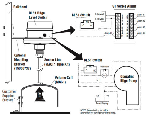
Installation Instructions
1. Select a mounting location in lower part of the bilge for the MAC1 air cell, but do not mount cell at this time. MAC1 must be placed so that no debris will become trapped inside it. Position the air cell approximately 1-1/2 to 2 in. (38 to 51 mm.) below desired operation point and note location for attaching the cell to a stringer or bulkhead, etc. Vertical adjustment may be necessary for final calibration (see step 6).

2. Mount the BLS1 switch via optional mounting bracket 15050737 or one of your supply. Keep the BLS1 switch within 4 ft. (1.21 m) off the MAC1 air cell. Tubing must NOT have a loop or flat area for moisture to collect. Always maintain a downward slope.
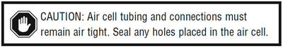
3. Attach the MACT1 tubing kit to the air cell and to the BLS1 switch. Any tubing can be used as long as it does not corrode and it provides air tight connections.
4. Wire the SPDT snap-switch according to instructions and your requirements. See typical wiring diagrams, below.
5. The BLS1 trip point is preset to operate when bilge level rises approximately 1-1/2 in. (38 mm.) above the bottom of the air cell. It will reset when level falls approximately 3/4 in. (19 mm.).
6. Raise or lower the air cell so that the distance from the hull to the trip point level on the side of the air cell is equal to desired level of bilge. Secure the air cell via the 2 hex bolts. If necessary, adjustment can be made prior to installation by placing the air cell in a bucket of water and adjusting the white knurled knob inside the BLS1 until the snap-switch actuates at the desired level. Or, build a coffer dam around the air cell in the bilge, add the desired amount of bilge water, and adjust the switch trip knob as explained above. BE SURE to remove coffer dam prior to placing the BLS1 into service.
7. Verify proper operation at desired levels prior to launch.
NOTE: The air cell will automatically recharge itself anytime the bilge level falls below the air cell.
How to Order the BLSK1To order use the model number designation diagram below.
|
Typical Installation and Wiring
|