STACKED FFU LEVER CONTROLLER
DESCRIPTION
This dual stacked lever controller provides full follow up control of the dual steering gear systems commonly found on Push Boats. These vessels are a regular sight on the Mississippi and adjoining river systems. One steering gear controls the steering rudders aft of the propellers and the other the flanking rudders forward of the propellers.
The 7195 is intended for use with electric over hydraulic steering systems. To complete the systems, a 7173-K steering amplifier, steering (directional control) solenoid valve and Rudder feedback unit complete with potentiometers and limit switches such as our 7174-A is required for each gear. For systems with more than one station, a transfer box and station selector switches at each station are also required.
Operating the FFU lever controller allows the hydraulic steering gear to move in the desired direction. When the handle is released, the FFU lever stays in that position (does not spring back to center) and the steering gear will continue to move (“FOLLOWING UP”) until it reaches that predetermined position, at which point the amplifier will stop the steering gear from moving further and holds at that position. The position of the rudders is proportional to the position of the FFU lever. Returning the lever to midship will cause the steering gear to “FOLLOW UP” to the midship position and stop and stay there until the next signal is given.
The 7195 is available with one potentiometer for each handle with a maximum of two potentiometers per handle and each handle includes a friction tensioning device. The top handle (usually for the flanking rudder system) also comes with a center detent. The standard handle length is 16” (18” from center of hub) but can be made shorter or longer on request. The controller (with the exception of switches and potentiometers) is constructed entirely of die cast bronze complemented by stainless steel hardware for longevity in a marine environment.
CAUTION: Before selecting FFU mode of steering control at a given station, align the steering lever with the position of the rudder. The lever must be within a few degrees of the rudder before selecting FFU mode at that station. The helm order indicator and rudder angle indicator must match before selecting FFU mode control.
Net weight: 9.5 lbs. (4.3 kg) approx.
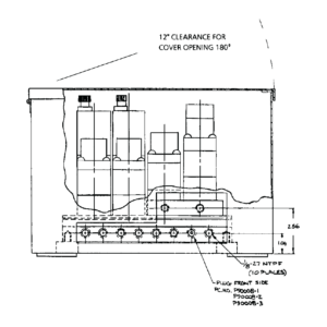
Dimensions: see other page
Options:
Finish – black or chrome
No. of potentiometer – one (standard) or PP – two potentiometer per handle
Description
Item | Qty | Part No. | Description | Item | Qty | Part No. | Description |
|---|---|---|---|---|---|---|---|
1 | 1 | 7195-0001 | Body | 15 | 2 | POT-1 | Potentiometer 1K |
2 | 2 | 7195-0002 | Handle | 16 | 2 | 6009-0005 | Terminal block |
3 | 2 | 7195-0003 | Bracket | 17 | 1 | 1201-0062 | Spring |
4 | 2 | 7195-0004 | Cam | 18 | 1 | 2012-0007 | Detent plunger |
5 | 1 | 7195-0005 | Shaft – long | 19 | 1 | 7195-0013 | Spacer |
6 | 1 | 7195-0006 | Shaft – short | 20 | 4 | 1010-0820 | Round head screw |
7 | 2 | 7195-0007 | Spacer – long | 21 | 4 | 1012-0606 | Pan head screw |
8 | 2 | 7195-0008 | Spacer – short | 22 | 2 | 1024-0824 | Spring Pin |
9 | 2 | 7195-0009 | Handle cap | 23 | 3 | 1016-1104 | Set screw |
10 | 2 | 7195-0010 | Handle tube | 24 | 2 | 2016-0011 | Friction plug |
11 | 2 | 7195-0011 | Handle grip | 25 | 2 | 1201-0002 | Spring |
12 | 2 | 7195-0012 | Key | 26 | 4 | 1016-0602 | Setscrew |
13 | 2 | Y-3220 | Brass gear | 27 | 4 | 1016-0603 | Setscrew |
14 | 2 | .YPB-3264 | Gear | 28 | 2 | 1002-1110 | Hex socket cap screw |
None.
None.