TACHOMETERS AND TACH/HOURMETERS
Series: ATS, ATA, ATHA, ATHS
3000 RPM – 0 to 100,000 Hours
Sensing from Magnetic Sensor Signal or Battery Charging Alternator
• High Visibility Analog Readout
• Air Core Movement
• Easy Calibration
• Through Dial Lighting
• Powered by 12 VDC Battery Converter for 24 to 12 VDC Available
Description
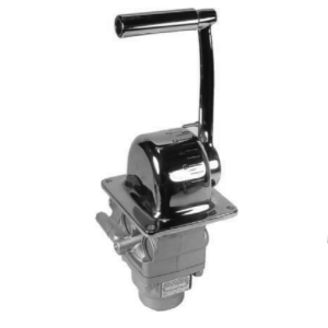
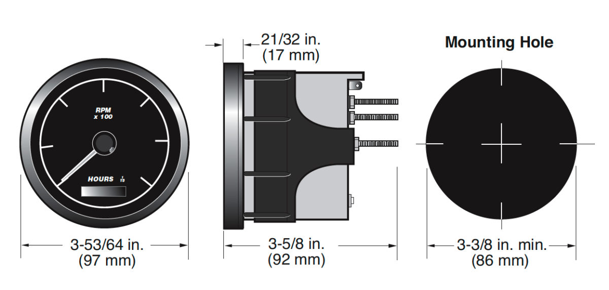
The tachometer is a rugged, transistorized instrument with solid-state circuitry for indication of engine revolutions per minute (RPM). It is equipped with a bracket for mounting into a standard 3-3/8 in. (86 mm.) dash mounting hole. The tachometer’s full 270° sweep of the pointer gives an accurate indication on a large easy–to–read scale. The dial can be illuminated for night reading. The models equipped with tachometer and hourmeter also record the elapsed running time of an engine.
Models for Alternator or Magnetic Sensor
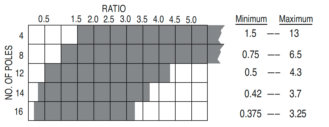
These instruments are designed to function from pulses generated by an alternator with 4, 8, 12, 14 or 16 poles on the rotor, or the pulses can be obtained from the ring gear of an engine by means of an electromagnetic sensor (magnetic pickup). Murphy’s magnetic sensor driven models are designed to function with flywheels having anywhere from 70 to 225 teeth.
All models are for negative ground, positive ground or isolated electrical systems and are protected against reverse polarity hookup. If the instrument is connected reverse polarity, it will not operate until proper connections are made. The tachometer is powered by 12 VDC.
Description
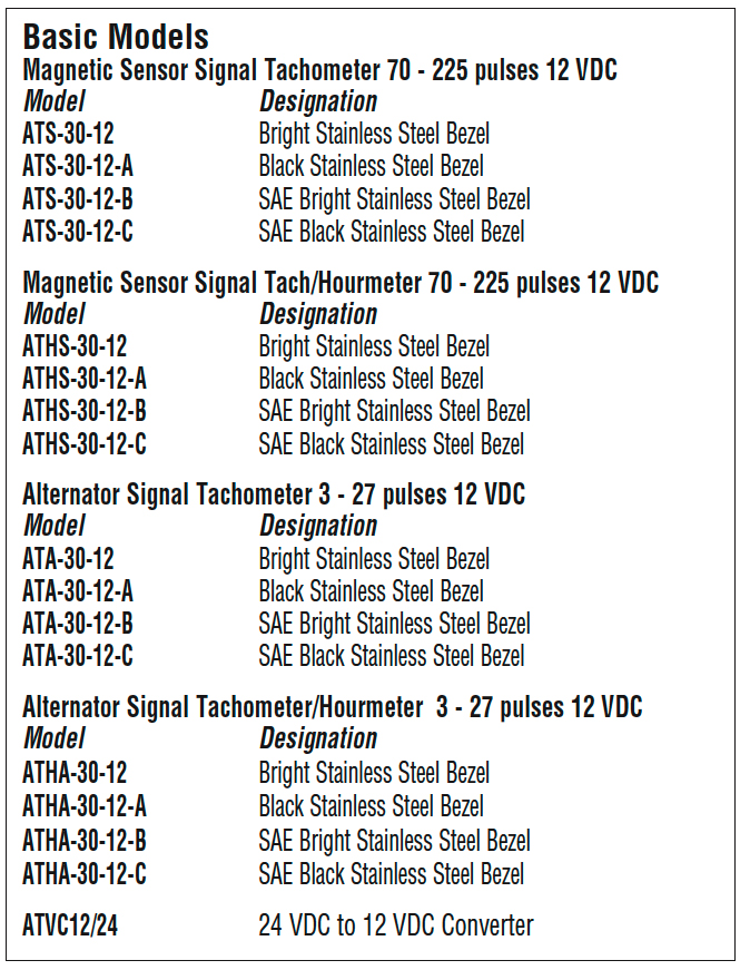
Basic Models
Magnetic Sensor Signal Tachometer 70 – 225 pulses* 12 VDC
Model & Designation
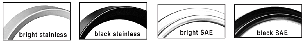
ATS-30-12 Bright Stainless Steel Bezel
ATS-30-12-A Black Stainless Steel Bezel
ATS-30-12-B SAE Bright Stainless Steel Bezel
ATS-30-12-C SAE Black Stainless Steel Bezel
Magnetic Sensor Signal Tach/Hourmeter 70 – 225 pulses* 12 VDC
Model & Designation
ATHS-30-12 Bright Stainless Steel Bezel
ATHS-30-12-A Black Stainless Steel Bezel
ATHS-30-12-B SAE Bright Stainless Steel Bezel
ATHS-30-12-C SAE Black Stainless Steel Bezel
Alternator Signal Tachometer 3 – 27 pulses* 12 VDC
Model & Designation
ATA-30-12 Bright Stainless Steel Bezel
ATA-30-12-A Black Stainless Steel Bezel
ATA-30-12-B SAE Bright Stainless Steel Bezel
ATA-30-12-C SAE Black Stainless Steel Bezel
Alternator Signal Tachometer/Hourmeter 3 – 27 pulses* 12 VDC
Model & Designation
ATHA-30-12 Bright Stainless Steel Bezel
ATHA-30-12-A Black Stainless Steel Bezel
ATHA-30-12-B SAE Bright Stainless Steel Bezel
ATHA-30-12-C SAE Black Stainless Steel Bezel
ATVC12/24 24 to 12 VDC Converter
Specifications
Power Input: 12 VDC (11.5 – 16 V)
RPM Input Signal Voltage: 1.5 Vrms minimum from a magnetic pickup or alternator (minimum 3-pole)
Accuracy: Tachometer: ± 2% full scale Hourmeter: ± 0.01% hours, ± 1 count
Temperature Range: -5°F to 185°F (-20°C to +85°C)
Dial (Face Plate): 270° sweep with white numerals (over black background)
Bezel: 304 Stainless Steel
Scale: 0-3000 RPM
Case Material: Plastic
Hourmeter Range: Measures elapsed time: 100,000 hours in 0.1 increments (tenths)
Shipping Weight: 0.89 lb. (403 g)
Shipping Dimensions: 5-1/2 x 5-1/2 x 5-1/2 in. (140 x 140 x 140 mm.)
Warranty
A one-year limited warranty on materials and workmanship is given with this Murphy product. Details are available on request and are packed with each unit.
|
Determine if the tachometer or tachometer/ hourmeter can be used for your application A. When used with magnetic sensor systems, the tachometer will operate from 70 to 225 tooth flywheels. 1. Determine the number of poles on your alternator. Look for the designation/type in the manufacturer’s manual or remove the pulley and fan to count the number of poles on the rotor. 3. Check that Pulley Ratio falls within the range shown on the Pulley Ratios Chart for a particular alternator. If ratio falls in the shaded area, the tachometer can be calibrated for the application. 4. To determine the pulses per engine revolution:
* Although the tach may be calibrated for higher input frequencies in some cases, as shown on the Pulley Ratio chart, pulley ratios in excess of 5.0 are NOT recommended nor are they normally used. |
 How to Order How to OrderOrder the Tachometer or Tachometer/Hourmeter by model designation. Example: ATA-30-12
|
||||||||||||||||||||||||||||||||||||||||||||||||||||||||||||||||||||||||||||||||||||||||||||||||||||||||||||||