NEWMAR BATTERY CHARGERS PHASE THREE SERIES
Three Stage “Smart” Chargers
Phase Three “Smart” battery charging technology is now available in a wide range of power levels, allowing you to select the right size, features and flexibility you require for virtually any application from small recreational craft to large live-aboards, workboats and other commercial vessels. These chargers inter-act with batteries to put them through the optimum three stage charge process which provides for fastest recovery and ideal conditioning, maximizing battery performance and extending battery life.
A selector switch adjusts output voltage to adapt for gel-cell/flooded lead-acid/AGM battery types. An optional temperature compensation sensor also adjusts output for ideal voltage based on changes in the batteries’ ambient temperature. All mod-els are housed in a rugged stainless steel case with a durable white powder coat finish, and the internal circuitry is poly-urethane coated for maximum corrosion resistance.
FEATURES
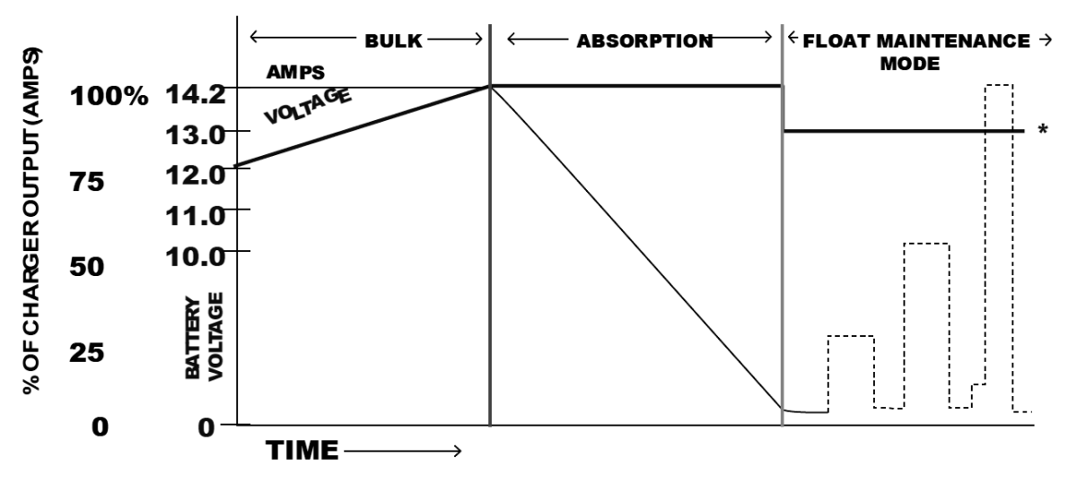
• “Smart” circuitry provides three stage charging—bulk, absorption, float.
• Wide model range covers battery system ratings from 14-950 amp-hours
• Gel-Cell/Flooded Lead-acid/AGM battery type switch selects optimum charge/float voltages.
• Multiple isolated output banks; ammeter indicates total output current. (except PT-7)
• Optional sensor adjusts output voltage based on battery temperature. (except PT-7)
• Current limiting-prevents damage from overloading.
• Charger status clearly displayed with L.E.D. and/or audible indicators or optional remote panel.
• Use as a power supply; can power loads without a battery in line.
• Built to last—rugged stainless steel case with a durable white powder coat finish with an optional drip shield and marinized internal circuitry.
• Numerous Safety and EMC Compliances
• Two year parts and labor warranty
Models
| 12 Volt | 24 Volt | 32 Volt |
|---|---|---|
| PT-7 | PT-24-8W | PT-32-25W |
| PT-14W | PT-24-13W | |
| PT-25W | PT-24-20W | |
| PT-40W | PT-24-45U | |
| PT-80 | PT-24-60W | |
| PT-24-95U | ||
| See below for detailed specifications. | ||
Description
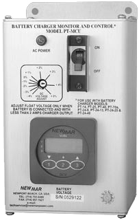
Phase Three Monitor/Control Unit For ABS Installation
This unit, when used in conjunction with certain PT Chargers* creates a system which is fully compliant with American Bureau of Shipping (ABS) Battery Charging standards for commercial installations.
* For use with all models except PT-7, PT-24-60W, PT-24-95U, and PT-32-25.
Incorporates
• Digital readout of float voltage to 1/10th volt
• Output float voltage adjustment pot; permits fine tuning from -4% to +5%
• AC circuit breaker; provides overcur rent protection and manual disconnect
• AC power ON indicator light
• 10’ wiring harness for easy connection of PT Series charger
Model: PT-MCU
Size (HxWxD ):8.7”x4.6”x5.5”
Weight :3.5 lbs.
Specifications
| 12 Volt Models | 24 Volt Models | |||||||||||
|---|---|---|---|---|---|---|---|---|---|---|---|---|
| PT-7 | PT-14 | PT-25 | PT-40 | PT-70A | PT-24-8 | PT-24-13 | PT-24-20 | PT-24-40 | PT-24-451 | PT-24-60F | PT-24-95F | |
| Input VAC | 88-132 or | 85-264 | 90-132 or | 85-135 or | 90-264 | 85-264 | 90-132 or | 85-135 or | 90-264 | 207-253 | 207-253 | 90-130 |
| (50-60 Hz.) | 176-264 | 180-264 | 170-270 | 180-264 | 170-270 | |||||||
| Input Amps @ Full Load | ||||||||||||
| @ 115 VAC | 2 | 2.8 | 6.5 | 8.5 | 12 | 2.8 | 6.5 | 8.5 | 12 | NA | NA | NA |
| @ 230 VAC | l | 1.4 | 4 | 4.3 | 6 | 1.4 | 4 | 4.3 | 6 | 8 | 13 | 17 |
| P.F. Rating | >.65 | .95@230V .98@115V | 0.7 | 0.7 | .95@230V .98@115V | .95@230V .98@115V | 0.7 | 0.7 | .95@230V .98@115V | 0.7 | 0.7 | 0.7 |
| Max Output Amps | ||||||||||||
| @ 115 VAC Innut | 7 | 14 | 25 | 40 | 64 | 8 | 13 | 20 | 37 | NA | NA | NA |
| @ 230 VAC Innut | 7 | 14 | 25 | 40 | 70 | 8 | 13 | 20 | 40 | 45 | 60 | 95 |
| Output Banks | 2 | 3 | 3 | 3 | 3 | 3 | 3 | 3 | 3 | 3 | 3 | 3 |
| Battery Capacity | ||||||||||||
| (Arnn-Hours) | 14-70 | 28-140 | 50-250 | 80-400 | 140-700 | 16-80 | 26-130 | 40-200 | 80-400 | 90-450 | 150-600 | 180-950 |
| Operating Temp. Rating Reference | T-2 | T-2 | T-2 | T-1 | T-2 | T-2 | T-2 | T-1 | T-2 | T-3 | T-3 | T-3 |
| Case Size Ref. | A-1 | A-2 | A-2 | A-3 | A-5 | A-2 | A-2 | A-3 | A-5 | A-4 | A-6 | A-6 |
| Weight: Lbs. /Kg. | 3.2/1.5 | 4-Aug | 8.2/4 | 6-Dec | 15.2/7 | 4-Aug | 8.2/4 | 6-Dec | 15.2/7 | 12.2/6 | 34.0/15 | 34.0/15 |
| Optional Temp. Sensor Model | NA | TCS-12/24 | TCS-12/24 | TCS-12/24 | TCS-12/24 | TCS-12/24 | TCS-12/24 | TCS-12/24 | TCS-12/24 | TP | TP | TP |
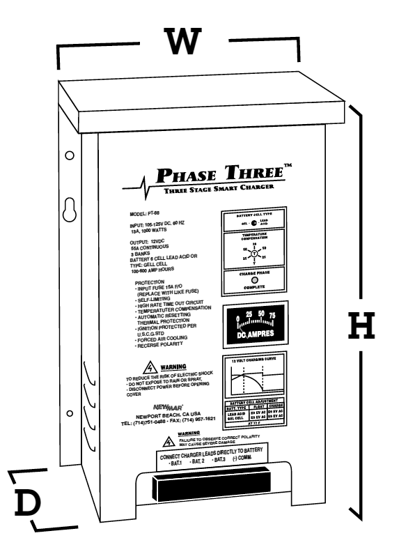
CASE SIZE
Inches | Centimeters | |||||
|---|---|---|---|---|---|---|
Ref | H | W | D | H | W | D |
A-1 | 10.5 | 5.0 | 2.8 | 26.7 | 12.7 | 7.1 |
A-2 | 12.5 | 7.7 | 4.3 | 31.8 | 19.6 | 10.9 |
A-3 | 14.1 | 9.5 | 4.0 | 35.8 | 24.1 | 10.2 |
A-4 | 15.5 | 9.7 | 5.0 | 39.4 | 24.6 | 12.7 |
A-5 | 16.7 | 9.8 | 6.7 | 42.4 | 24.9 | 17.0 |
A-6 | 19.5 | 12.2 | 8.2 | 49.5 | 40.0 | 20.8 |
Temperature Rating References:
T-1 -10°C to +45°C; Derate linearly from 100% @ 0°C to 80% @ -10°C
T-2 -10°C to +60°C; Derate linearly from 100% @ 40°C to 60% @ 60°C
T-3 -10°C to +60°C; Derate linearly from 100% @ 50°C to 60% @ 60°C
T-4 -10°C to +60°C; Derate linearly from 100% @ 40°C to 60% @ 60°C
T-5 -40°C to +60°C; Derate linearly from 100% @ 50°C to 75% @ 60°C
T-6 -20°C to +50°C; Full output
T-7 -20°C to +70°C; Derate linearly from 100% @ 45°C to 50% @ 70°C
T-8 -20°C to +70°C; Derate linearly from 100% @ 50°C to 50% @ 70°C
Compliance References*:
See matrix for applicable models
CG USCG CFR 183.410 (Ignition protected)
EN EN 60335-1, EN 60335-2-29
CE Carries the CE Mark
* Numerous other Safety and EMC compliances may also apply. Contact factory if further compliance information is required.
Output Indicator References:
M-1 Charge/Float L.E.D.
M-2 Total output ammeter and charger status L.E.D.’s/Alarms
M-3 Total output ammeter and power-on L.E.D.
Typical Charge Curve:
Nominal Output Voltages at Gel/Flooded Switch Settings
(without Temperature Compensation option installed or at 22.2˚C (72˚F) with Temperature Compensation option installed.)
12 Volt Models | 24 Volt Models | 32 Volt Model | ||||
|---|---|---|---|---|---|---|
Charge | Float | Charge | Float | Charge | Float | |
Setting | @ 50 % load | @ .5 amp load | @ 50 % load | @ .5 amp load | @ 50 % load | @ .5 amp load |
Gel-Cell | 14.0 VDC | 13.6 VDC | 28.0 VDC | 27.2 VDC | 37.3 | 36.2 |
Flooded/AGM | 14.2 VDC | 13.4 VDC | 28.4 VDC | 26.8 VDC | 37.8 | 35.7 |
Temperature Compensation:
5mV per cell per ˚C. Sensor supplied with 25′ cable (40’ cable optional) and plug-in connector
Protection (all models):
Input/Output Fuses, Current Limiting, Thermal Protection, Forced Air Cooling, Drip Shield
Remote Panel, Model RP:
LED’s indicate charger output stage. Manual reset button reinitializes three stage charge cycle. Supplied with 25′ cable and plug-in connector. Panel dimensions: 3″ H x 4.75″ W